FiberMaxHP Multi-Axis Photonics Alignment System
The FiberMax®HP is a second-generation three- to six-axis photonics alignment platform built on Aerotech’s ANT nanopositioning product line. It is designed to meet the demanding needs of critical photonics alignment in a highly automated, 24/7 production environment with no compromise in speed, accuracy and resolution.
Description
Specifications
Dimensions
Ordering Info
Downloads
Description
Description
Specifications
Dimensions
Ordering Info
Downloads
Description
Design Feature
- 2nd-generation photonics alignment platform built on high-performance ANT nanopositioners
- Up to 6 axes of precision motion
- Proven reliability for 24/7 manufacturing
- Noncontact, direct-drive for all axes enabling high-throughput alignment
- Minimum incremental motion to 2 nm on linear motion and 0.05 μrad on rotary motion
- Powerful controls with standard scanning algorithms and virtual pivot-point kinematics
- Flexible design with many standard configurations and options
- Interface to industry-standard power meters
Aerotech’s FiberMax®HP represents a significant breakthrough in the high-volume manufacturing and testing of photonics components, reflecting more than 40 years of experience in designing advanced positioning systems for OEMs and end-users in the high-technology industries.
A highly repeatable, precise, and industrial-grade positioning system is the foundation for high-volume manufacturing and testing of photonics components. FiberMaxHP’s highly reliable, unique drive and control technologies ensure many years of maintenance-free service in a high throughput, 24/7 manufacturing environment.
Ultra-Precision Direct-Drive
As alignment tolerances become smaller with new silicon photonics devices, the requirement for high-speed and high-accuracy alignment is essential. FiberMaxHP noncontact direct-drive technology enables high-precision alignment without sacrificing production throughput. Capable of minimum incremental motion down to 2 nm coupled with speeds to 400 mm/s, the FiberMaxHP meets the challenges of aligning next-generation photonics packages.
The direct-drive technology employed in FiberMaxHP offers a significant precision and throughput advantage over other alignment platforms.
Powerful Kinematics and Scanning Routines
Aerotech’s controllers work with a variety of smart cameras and machine vision systems to help facilitate first light. Our power servo scanning algorithms can be called to optimize power coupled through the devices. Standard scanning routines include fast align, hill climb, spiral, and raster searches in up to six axes of motion.
Our advanced kinematics enable a virtual pivot point where rotation can occur at any user-defined point in space rather than the physical rotation point of the FiberMaxHP axes. This assists the speed and accuracy of active alignment. We have an extensive range of software and hardware options to suit your specific needs.
Flexible System Configuration
The FiberMaxHP is available with three- to six-axes of direct-drive alignment axes allowing the platform to be specified with the exact number of axes needed for the application. Since many applications require manual adjustment of fixtures and parts for a one-time initial alignment, the FiberMaxHP comes with one- to three-axes of manual angular alignment axes with ±2° of motion. These manual adjustment axes mount directly to the direct-drive platform and offer a more economical approach to alignment when adjustment is not frequently required.
Aerotech has many years of experience providing solutions to the photonics industry. We realize that your application may be unique and require customization. The FiberMaxHP is a modular design and can be easily customized with special arrangement of axes, fixturing, and mounting patterns to meet the needs of your specific application.
FiberMaxHP |
-ZXY |
-ZXYT |
-ZXYR |
-ZXYP |
| Travels | X: 50 mm Y: 3 mm Z: 50 mm |
X: 50 mm Y: 3 mm Z: 50 mm T: 20 deg |
X: 50 mm Y: 3 mm Z: 50 mm R: 20 deg |
X: 50 mm Y: 3 mm Z: 50 mm P: 20 deg |
| Accuracy - Base Performance (-PL1)(2,3) | X: ±3.0 μm Y: ±2.0 μm Z: ±3.5 μm |
X: ±4.2 μm Y: ±2.0 μm Z: ±4.7 μm T: ±25 μrad |
X: ±4.2 μm Y: ±2.0 μm Z: ±4.7 μm R: ±90 μrad |
X: ±4.2 μm Y: ±2.0 μm Z: ±4.7 μm P: ±90 μrad |
| Accuracy - Base Performance (-PL3)(2,3) | X: ±300 nm Y: ±200 nm Z: ±300 nm |
X: ±300 nm Y: ±200 nm Z: ±300 nm T: ± 8 μrad |
X: ±300 nm Y: ±200 nm Z: ±300 nm R: ±30 μrad |
X: ±300 nm Y: ±200 nm Z: ±300 nm P: ±30 μrad |
| Resolution (Min. Incremental Motion) | 2 nm | X/Y/Z: 2 nm T: 0.05 μrad |
X/Y/Z: 2 nm R: 0.25 μrad |
X/Y/Z: 2 nm P: 0.25 μrad |
| Bidirectional Repeatability(3) | ±150 nm | X/Z: ±175 nm Y: ±150 nm T: ±3.5 μrad |
X/Z: ±175 nm Y: ±150 nm R: ±18 μrad |
X/Z: ±175 nm Y: ±150 nm P: ±18 μrad |
| Maximum Speed(4) | X: 400 mm/s Y: 75 mm/s Z: 200 mm/s |
X: 400 mm/s Y: 75 mm/s Z: 200 mm/s T: 120 deg/s |
X: 400 mm/s Y: 75 mm/s Z: 200 mm/s R: 150 deg/s |
X: 400 mm/s Y: 75 mm/s Z: 200 mm/s P: 150 deg/s |
| Load Capacity(5) | 2 kg | 1.5 kg | 1.5 kg | 1.5 kg |
| Stage Mass | 6.0 kg | 7.5 kg | 6.5 kg | 6.5 kg |
| Material | Anodized Aluminum | Anodized Aluminum | Anodized Aluminum | Anodized Aluminum |
| MTFB (Mean Time Between Failure) | 30,000 Hours | 30,000 Hours | 30,000 Hours | 30,000 Hours |
FiberMaxHP |
-ZXYTR |
-ZXYTP |
-ZXYTPR |
| Travel | X: 50 mm Y: 3 mm Z: 50 mm T: 20 deg R: 20 deg |
X: 50 mm Y: 3 mm Z: 50 mm T: 20 deg P: 20 deg |
X: 50 mm Y: 3 mm Z: 50 mm T: 20 deg P: 20 deg R: 20 deg |
| Accuracy - Standard(2,3) | X: ±5.5 μm Y: ±2.0 μm Z: ±6.0 μm T: ±25 μrad R: ±90 μrad |
X: ±5.5 μm Y: ±2.0 μm Z: ±6.0 μm T: ±25 μrad P: ±90 μrad |
X: ±6.5 μm Y: ±2.0 μm Z: ±7.0 μm T: ±25 μrad P/R: ±90 μrad |
| Accuracy - PLUS(2,3) | X: ±350 nm Y: ±200 nm Z: ±350 nm T: ±8 μrad R: ±30 μrad |
X: ±350 nm Y: ±200 nm Z: ±350 nm T: ±8 μrad P: ±30 μrad |
X: ±400 nm Y: ±200 nm Z: ±400 nm T: ±8 μrad P/R: ±30 μrad |
| Resolution (Min. Incremental Motion) | X/Z: 3 nm Y: 2 nm T: 0.05 μrad R: 0.25 μrad |
X/Z: 3 nm Y: 2 nm T: 0.05 μrad P: 0.25 μrad |
X/Z: 4 nm Y: 2 nm T: 0.05 μrad P/R: 0.25 μrad |
| Bidirectional Repeatability(3) | X/Z: ±200 nm Y: ±150 nm T: ±3.5 μrad R: ±18 μrad |
/Z: ±200 nm Y: ±150 nm T: ±3.5 μrad P: ±18 μrad |
X/Z: ±250 nm Y: ±150 nm T: ±3.5 μrad P/R: ±18 μrad |
| Maximum Speed(4) | X: 400 mm/s Y: 75 mm/s Z: 200 mm/s T: 120 deg/s R: 150 deg/s |
X: 400 mm/s Y: 75 mm/s Z: 200 mm/s T: 120 deg/s P: 150 deg/s |
X: 400 mm/s Y: 75 mm/s Z: 200 mm/s T: 120 deg/s P/R: 150 deg/s |
| Load Capacity(5) | 1 kg | 1 kg | 1 kg |
| Stage Mass | 8.0 kg | 8.0 kg | 9.0 kg |
| Material | Anodized Aluminum | Anodized Aluminum | Anodized Aluminum |
| MTFB (Mean Time Between Failure) | 30,000 Hours | 30,000 Hours | 30,000 Hours |
Option |
Description |
| Drive System | Brushless Servomotor |
| Feedback | Noncontact Linear Encoder |
| Maximum Bus Voltage | 80 VDC |
| Limit Switches | 5 V, Normally Closed |
| Home Switch | Near Center of Travel |
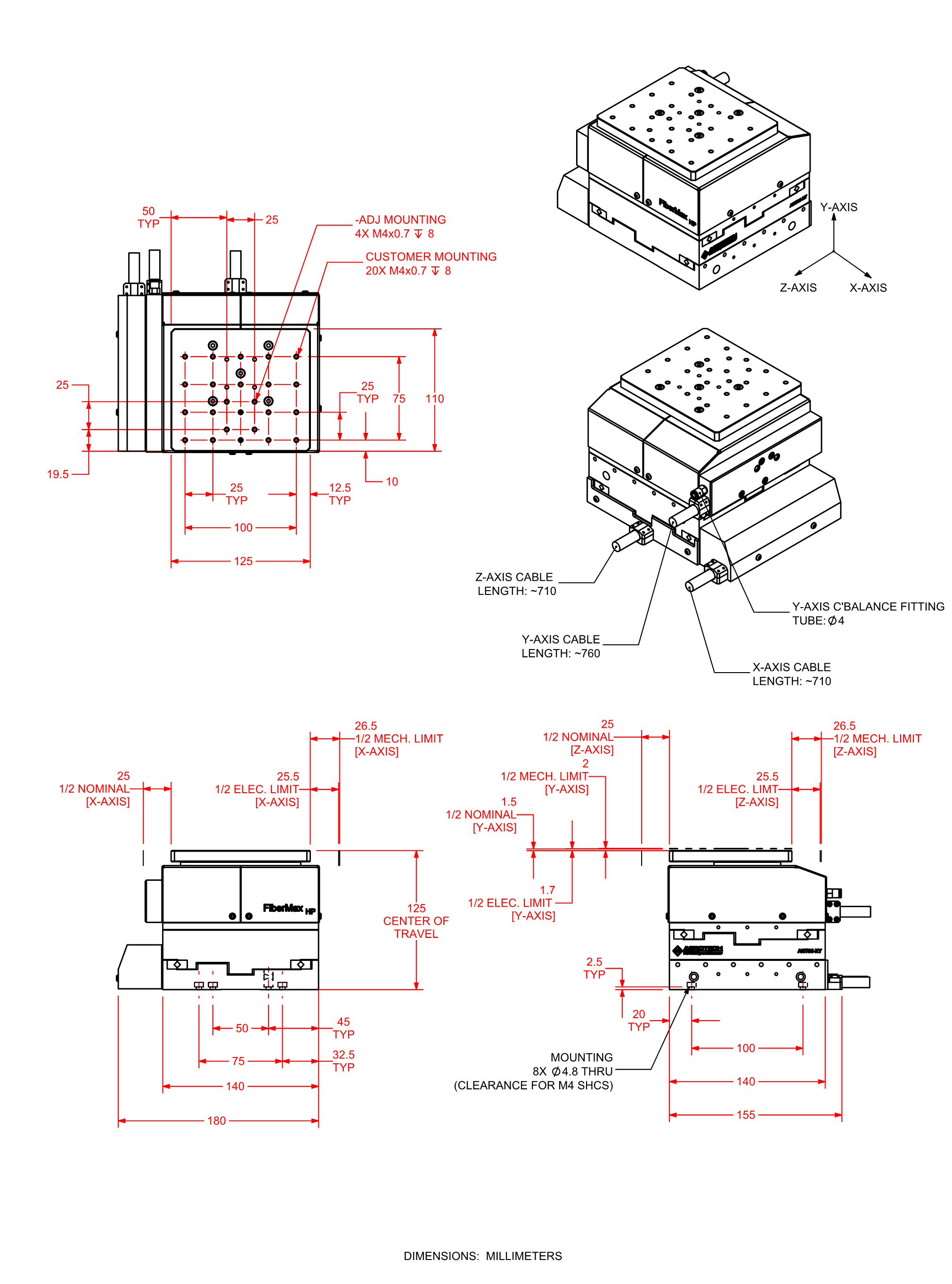
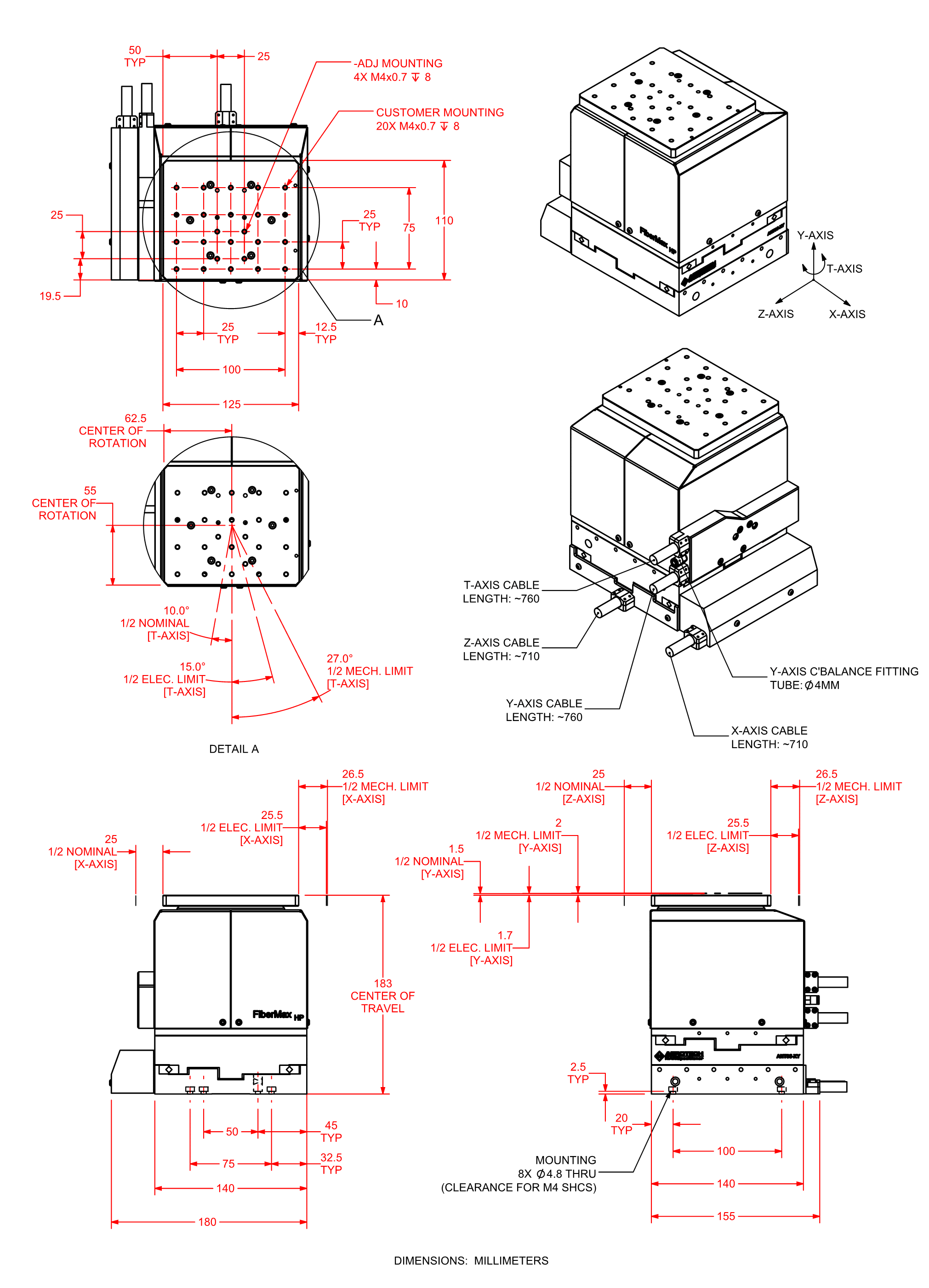
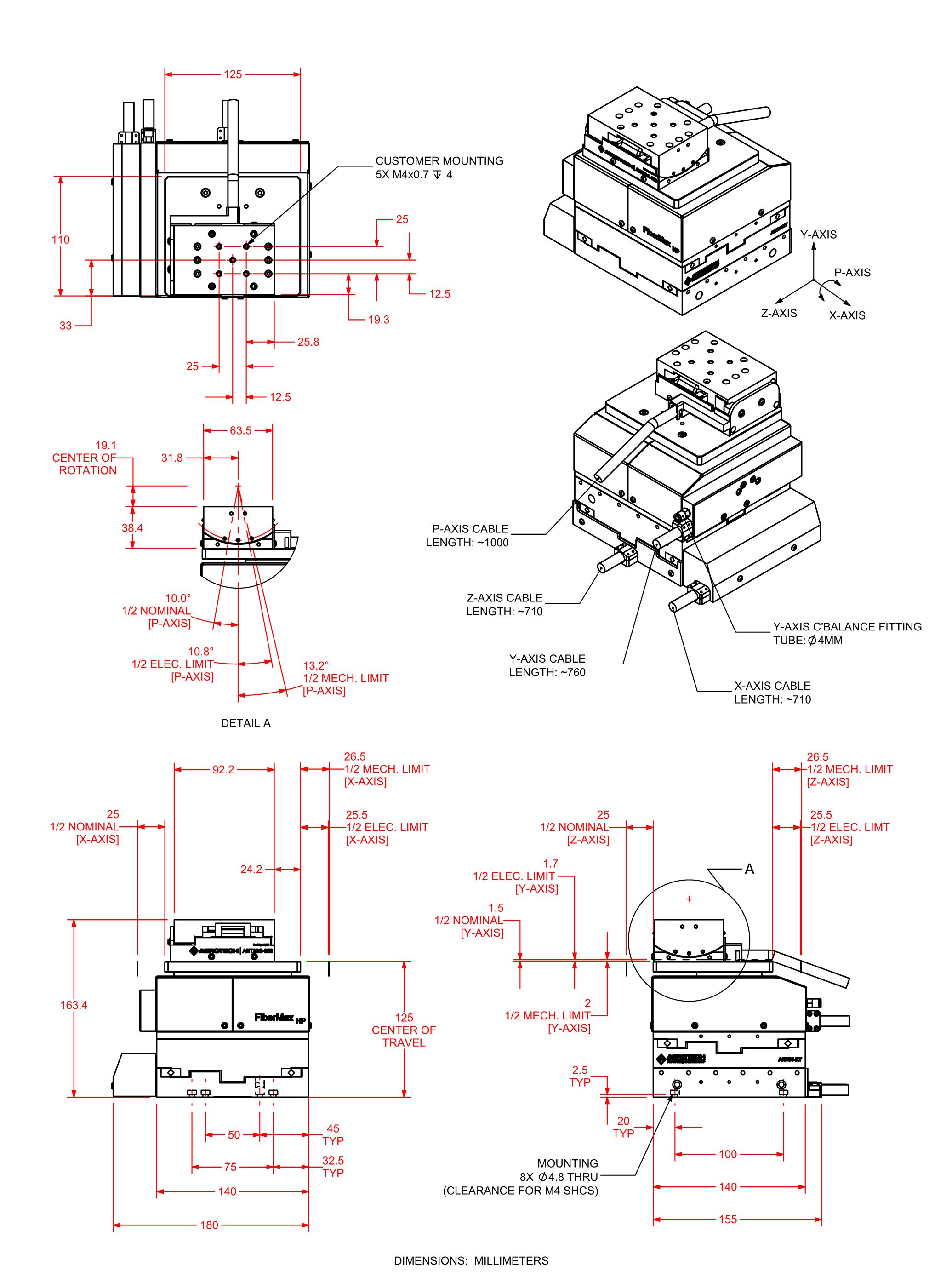
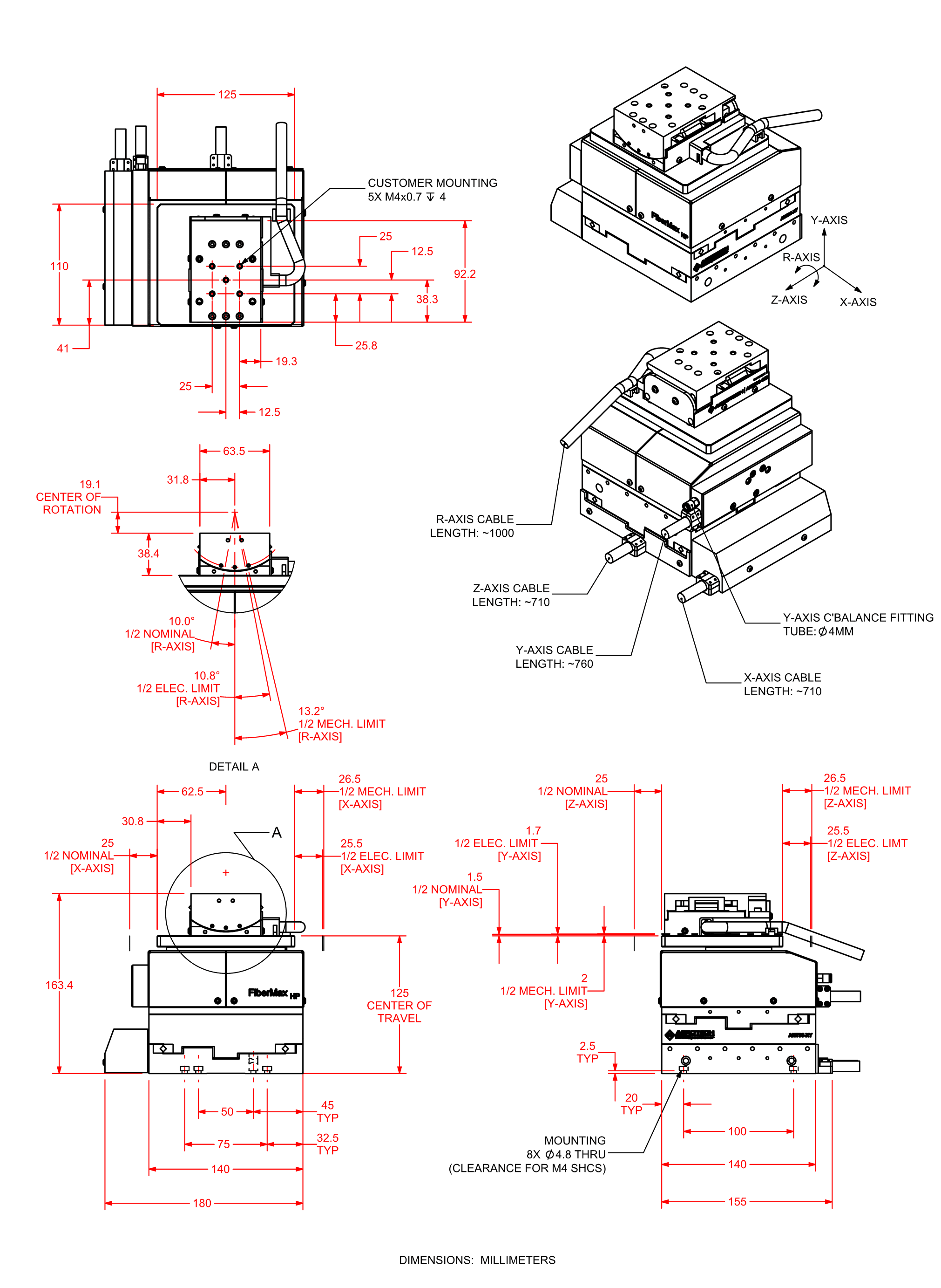
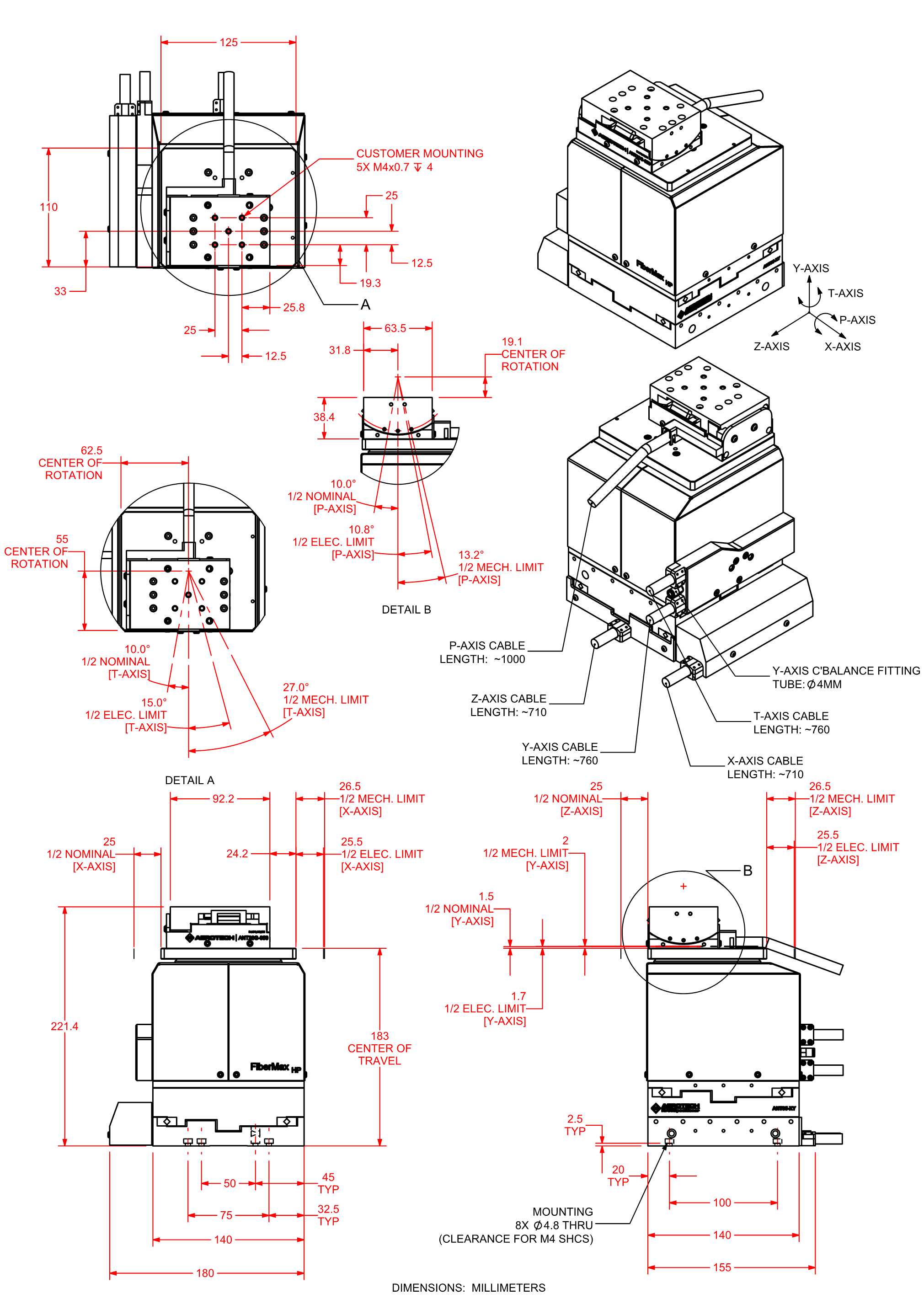
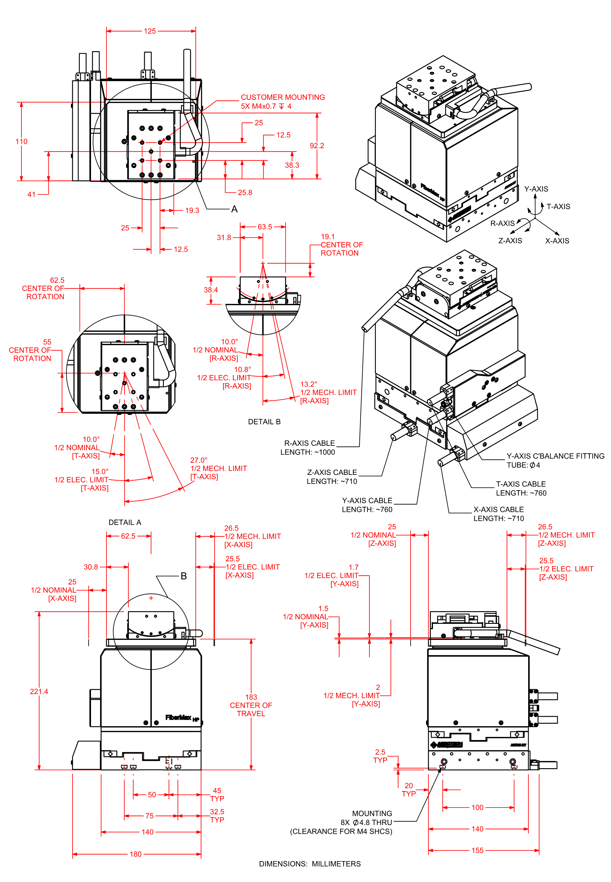
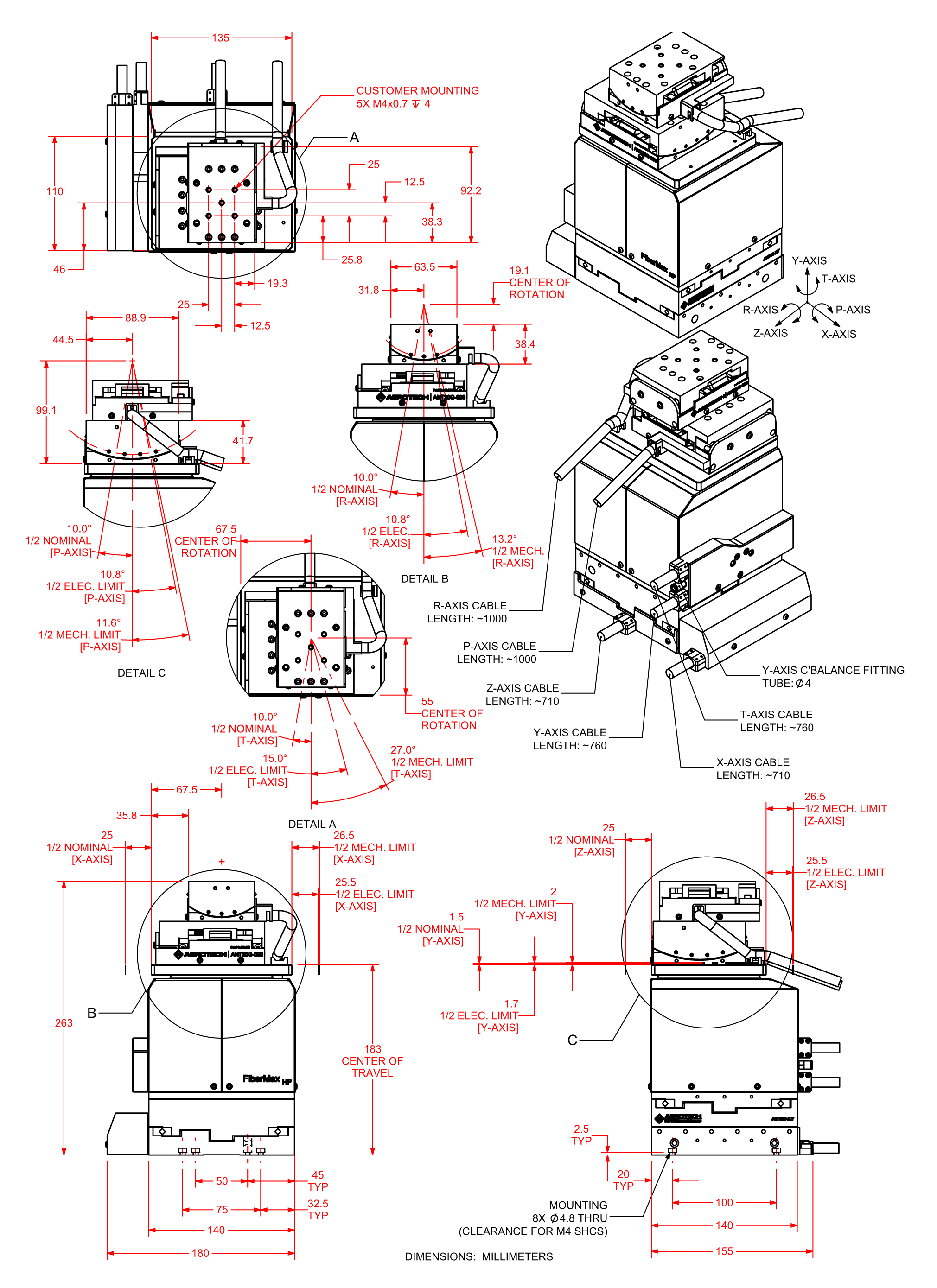
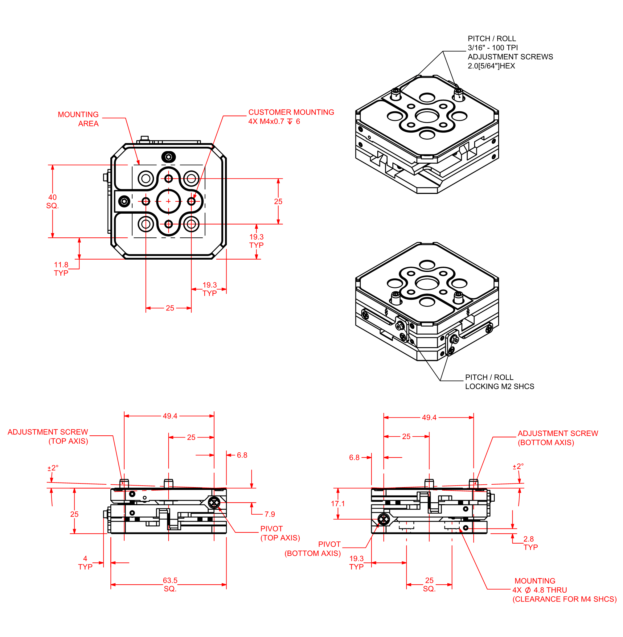
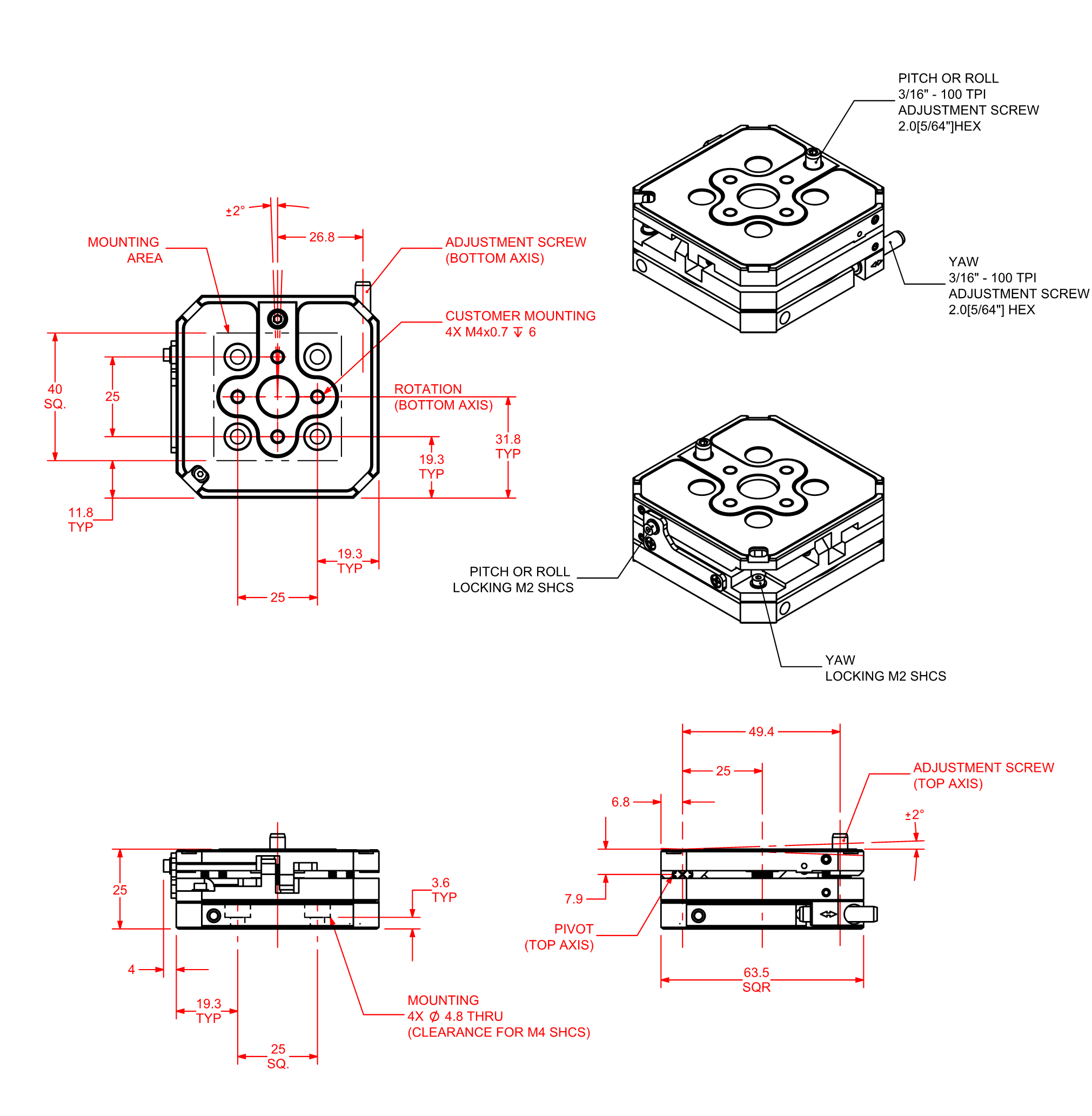
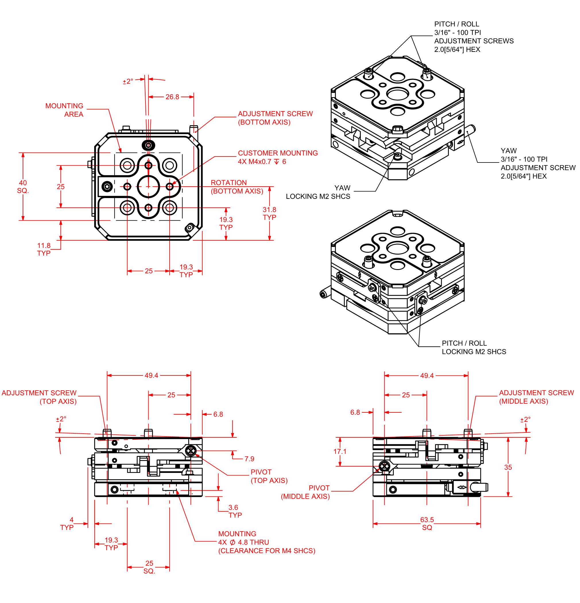
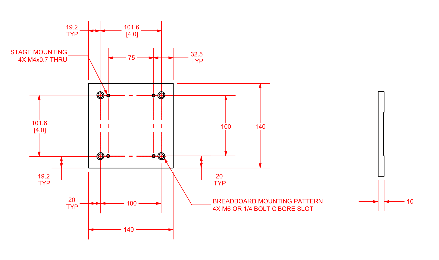
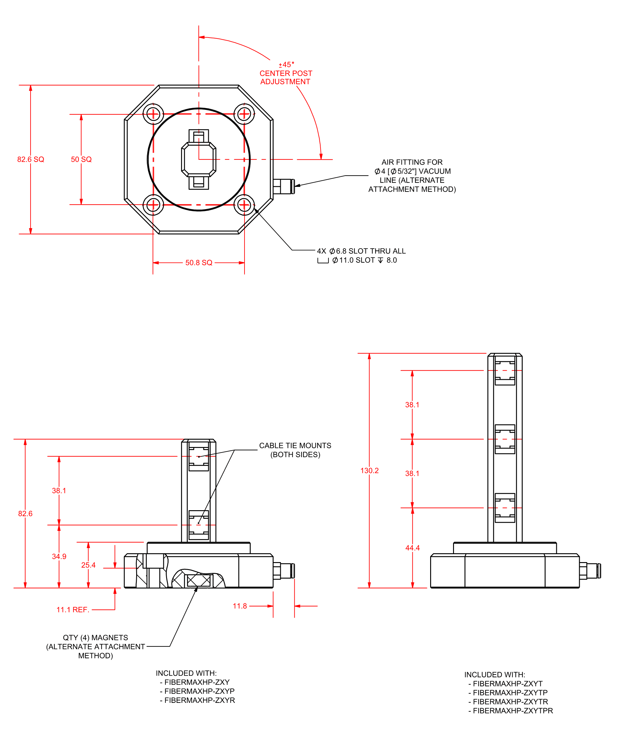
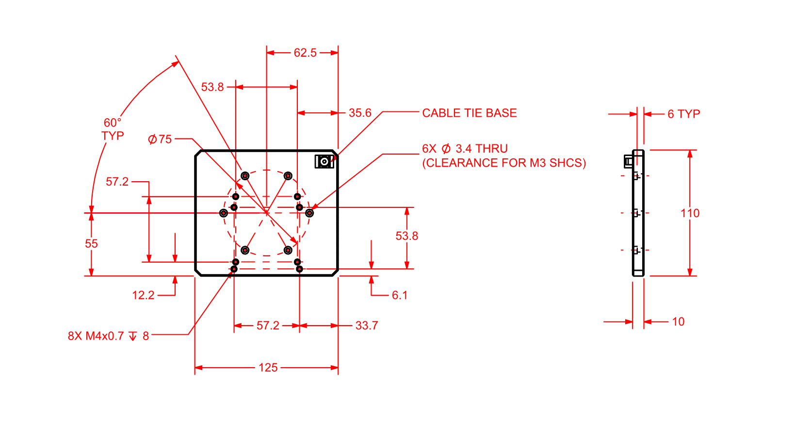
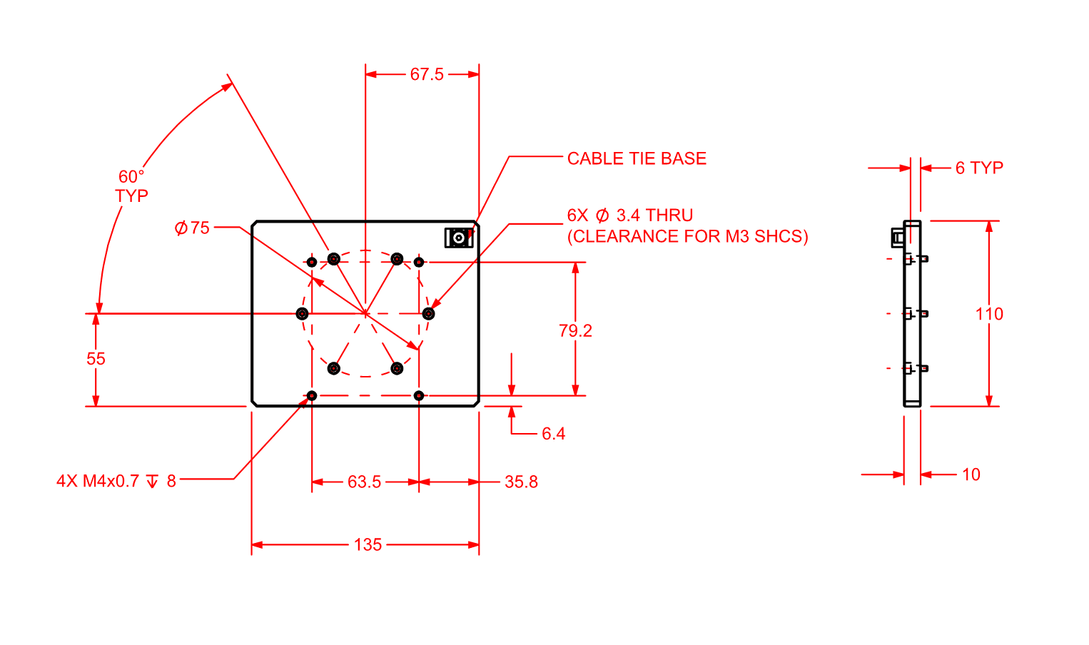
Dimensions
FiberMaxHP-ZXY
FiberMaxHP-ZXYT
FiberMaxHP-ZXYP
FiberMaxHP-ZXYR
FiberMaxHP-ZXYTP
FiberMaxHP-ZXYTR
FiberMaxHP-ZXYTPR
MADJ-AT1
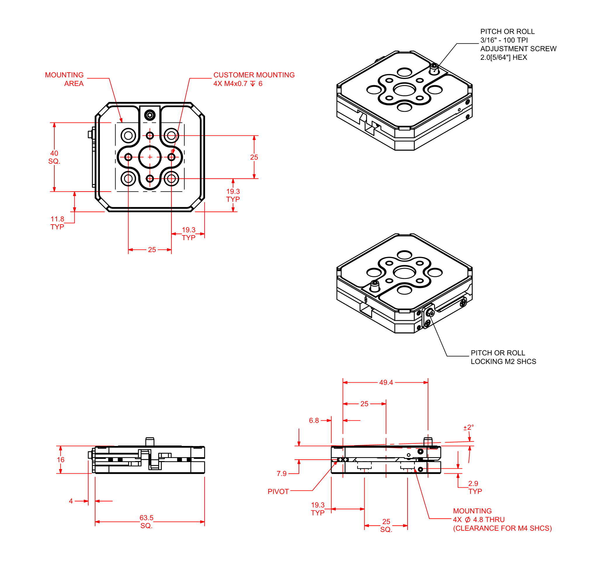
MADJ-AT2
MADJ-AT3
MADJ-AT4
FiberMaxHP-MP
FiberMaxHP-ACP
AP-ANT95R-ANT20G-50
AP-ANT95R-ANT20G-90
Ordering Information
FiberMaxHP Multi-Axis Photonics Alignment System
Axis Configuration (Required)
| Option | Description |
| -ZXY | 3-axis platform (Z, X, Y) |
| -ZXYT | 4-axis platform (Z, X, Y, Theta) |
| -ZXYP | 4-axis platform (Z, X, Y, Pitch) |
| -ZXYR | 4-axis platform (Z, X, Y, Roll) |
| -ZXYTP | 5-axis platform (Z, X, Y, Theta, Pitch) |
| -ZXYTR | 5-axis platform (Z, X, Y, Theta, Roll) |
| -ZXYTPR | 6-axis platform (Z, X, Y, Theta, Pitch, Roll) |
Manual Adjustment (Optional)
| Option | Description |
| -ADJ1 | 3-axis manual angular adjustment (±2 deg), Yaw/Pitch/Roll |
| -ADJ2 | 2-axis manual angular adjustment (±2 deg), Pitch/Roll |
| -ADJ3 | 2-axis manual angular adjustment (±2 deg), Yaw/Pitch |
| -ADJ4 | 2-axis manual angular adjustment (±2 deg), Yaw/Roll |
| -ADJ5 | 1-axis manual angular adjustment (±2 deg), Pitch |
| -ADJ6 | 1-axis manual angular adjustment (±2 deg), Roll |
Mounting Plate (Optional)
| Option | Description |
| -MP1 | Mounting plate for optical table mounting |
Performance Level (Required)
| Option | Description |
| -PL1 | Base performance |
| -PL3 | High-accuracy performance, PLUS |
Integration (Required)
Aerotech offers both standard and custom integration services to help you get your system fully operational as quickly as possible. The following standard integration options are available for this system. Please consult Aerotech if you are unsure what level of integration is required, or if you desire custom integration support with your system.
| Option | Description |
| -TAS | Integration - Test as system Testing, integration, and documentation of a group of components as a complete system that will be used together (ex: drive, controller, and stage). This includes parameter file generation, system tuning, and documentation of the system configuration. |
| -TAC | Integration - Test as components Testing and integration of individual items as discrete components that ship together. This is typically used for spare parts, replacement parts, or items that will not be used together. These components may or may not be part of a larger system. |
Accessories (Ordered as Separate Line Item)
| Option | Description |
| AP-ANT95R-ANT20G-50 | Adapter plate, ANT95R to ANT20G-50 |
| AP-ANT95R-ANT20G-90 | Adapter plate, ANT95R to ANT20G-90 |
Manual Angular Adjustment Stages
| Option | Description |
| MADJ-AT1 | 1-axis, Pitch or Roll (±2 deg) |
| MADJ-AT2 | 2-axis, Pitch/Roll (±2 deg) |
| MADJ-AT3 | 2-axis, Yaw/Pitch or Yaw/Roll (±2 deg) |
| MADJ-AT4 | 3-axis, Yaw/Pitch/Roll (±2 deg) |