Application Note, Motion Control Platforms
Application Note
Automation1 Motion Control Platform Improves Laser Scan System Tracking Performance
Precision laser scanning systems are characterized by their ability to perform challenging contoured motion while maintaining the desired path position. One might refer to this as the “minimal tracking error” or “minimal following error.” Many factors are involved in delivering high-throughput, highly-accurate laser scanning systems. For simplicity, there are two main technical components that must work together to deliver this performance:
- The mechanical solution – the laser scan head itself.
- The control solution – the motion controller and drive system for the laser scan head.
A laser scan head is typically composed of two mirrors, each directly coupled to its own galvanometric, servo controlled motor with a precision feedback device. The design of these motor-mirror-feedback assemblies and the associated mechanical support structure sets a baseline for the potential performance of the overall system. For the sake of the tests described in this application note, the same mechanical setup was used to compare two different control platforms.
The control solution begins with a motion controller translating a desired trajectory (often described in arcs and lines using the G-Code programming language) into a series of control points (called ‘trajectory points’) that are then sent to independent servo controllers – one for each motor. These points are the input to the servo controllers, which interpolate the points to match the rate of the servo control loop’s operation. To achieve highly accurate vector motion, each independent servo controller must receive and use these command positions synchronized in time. This synchronized control enables coordination of the power amplifiers and therefore of the motion of each motor in the laser scan head, ultimately supplying precise vector laser spot placement to a process. The ability of the new Automation1 motion control platform is compared with the ability of the industry established A3200 motion control platform for the sake of controlling an AGV20HP-2 galvo scanner. See Table 1 for a comparison of the systems.
Table 1. Comparison of the Automation1 and the A3200 control systems being tested in this application note.
| Table 1 | Automation1 Platform | A3200 Platform | |
|---|---|---|---|
| Input Trajectory | 10x10 degree square pattern with 0.5 deg radius at the corners, commanded at 1000 deg/s(1) | ||
| Tests | Test #1: The motion controller translates the trajectory into servo control points without applying finite impulse response (FIR) filtering. Test #2: The motion controller translates the trajectory into servo control points and concurrently applies a finite impulse response (FIR) filter during this translation. | ||
| Motion Controller | Automation1-iSMC Intelligent Software-based Machine Controller | A3200 SMC Software-based Machine Controller | |
| Trajectory Rate | 100 kHz | 48 kHz | |
| Motion Bus | Automation1 HyperWire | A3200 FireWire over HyperWire | |
| Drive Electronics | Automation1-GL4 with 200kHz servo controller | Automation1-GL4 with 192 kHZ servo controller | |
| Trajectory to Servo Interpolation Rate | 1:2 | 1:4 | |
| Laser Scan Head | AGV20HP | AGV20HP | |
- The trajectory is specified in mechanical degrees (mirror rotation) and not optical degrees of the laser beam.
As Table 1 shows, the Automation1 motion controller generates trajectory points at more than double the rate of the A3200 controller. This enables the Automation1-GL4 to increase its servo control rate by 4.2% (from 192 kHz to 200 kHz) and decrease the required interpolation rate from 1:4 to 1:2.
Laser Scan Head Performance Testing
Laser scan heads typically utilize special optics to translate the rotational motion of the mirror to linear motion of a laser spot along a substrate. The tests being performed in this note are simply measuring the position of each motor that drives the separate mirrors. They are not measuring the actual performance of the physical laser process. Instead, these tests assume that increased performance of positioning the motor, as per the encoder feedback, will translate into overall improved system level performance.
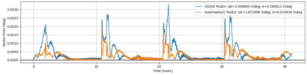
The first test shows a comparison of performance with the motion controller running the trajectory described above without applying a finite impulse response (FIR) filter during the translation. The second test includes the FIR filter applied by each motion controller. On each controller, the number of FIR filter taps were selected to have a servo loop frequency response roll off similar to higher frequency content.
Table 2. Test #1 - No FIR Filtering - position error for the described trajectory as read by the motor encoders.
| Description | Units | Automation1 | A3200 | Automation1 Improvement |
|---|---|---|---|---|
| XY Vector-Axis Position Error, Pk-Pk | mdeg | 2.872093 | 3.483799 | 17.56% |
| XY Vector-Axis Position Error, Std. Dev. | mdeg | 0.287080 | 0.653970 | 56.10% |
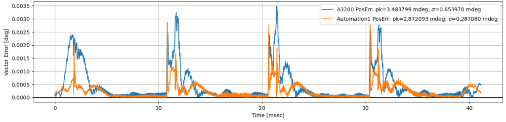
Table 3. Test #2 - FIR Filtering Applied - position error for the described trajectory as read by the motor encoders.
| Description | Units | Automation1 | A3200 | Automation1 Improvement |
|---|---|---|---|---|
| XY Vector-Axis Position Error, Pk-Pk | mdeg | 1.872906 | 3.300665 | 43.26% |
| XY Vector-Axis Position Error, Std. Dev. | mdeg | 0.254938 | 0.569312 | 55.22% |
Summary
In summary, the increased trajectory rate, increased servo rate and lowered required interpolation rate of the Automation1 motion control platform for laser scan head systems leads to noticeable improvements in what is often referred to as “tracking” or “following” contoured motion performance.