Automation1 iXR3 Multi-Axis Servo Drive Rack with Motion Controller
The Automation1 iXR3 is two solutions in one: a high-performance, six-axis drive rack with an integrated motion controller—meaning it’s capable of complete machine control—and a multi-axis servo motor drive rack with configurable and field-replaceable, front-mounted amplifier cards.
The iXR3 runs the full Automation1-iSMC motion controller, offers industry-best sub-nanometer levels of position control for servo motors and stages, connects to other Automation1 drives over HyperWire and connects to other automation devices over EtherCAT, EtherNet/IP™, Modbus TCP/IP or a TCP Socket interface. Multi-axis PSO enables precision control of your industrial laser or process tool synchronized with your motion trajectory.
Description
Specifications
Dimensions
Ordering Info
Downloads
Description
Description
Specifications
Dimensions
Ordering Info
Downloads
Description
Design Features
- Unlock the full motion control power of our Automation1-iSMC intelligent software-based motion controller
- Features complete configuration & performance capability of the XR3 drive rack
- Connect to the controller using EtherCAT, EtherNet/IP, Modbus or a Socket interface
- Plug-in amplifiers with dedicated control cards drive brush, brushless, stepper, voice coil or piezo motors
- Enjoy up to 12 axes of control by connecting more Automation1 drives over the HyperWire fiber-optic bus
- Includes PSO, the ultimate in position-based control for industrial lasers, cameras & more
- Features safe torque off (STO) functional safety (certification pending)
Machine Control That Stands Alone
The iXR3 motor circuits are driven by powerful controller cards that close the servo and current loops at 20 kHz. These cards also provide several other high-speed, low latency control features to improve the throughput and quality of your process. The iXR3 unit processes digital and analog I/O, high-speed data collection, highspeed differential outputs, position synchronized outputs and encoder multiplication functionality in real-time. EtherCAT, EtherNet/IP, Modbus TCP and a Socket interface enable true full machine and motion system control with this device.
Automation1
The iXR3 is a part of the user-friendly Automation1 motion control platform, which includes the following:
Standard drive features for the iXR3 include per-axis brake control logic, auxiliary encoder feedback and analog I/O expansion. Also standard are 16 opto-isolated inputs, 16 opto-isolated outputs, up to 12 high-speed differential outputs, 3 PSO external sync inputs, 3 TTL or isolated PSO outputs, 1 opto-isolated data-acquisition input and 2 STO sense inputs.
Configuration options for the iXR3 include three different levels of integrated encoder multiplication, cooling options, mounting options and options for low-latency, position-based process control (PSO).
The iXR3 can be configured with either PWM or linear plug-in amplifiers for the control of brushless, DC brush, or stepper motors at up to 320 VDC operating voltage and 30 A peak current capability. Bus power customization is possible through two separate and configurable motor power supply circuits, allowing a variety of motors to be integrated with the iXR3. When only one motor voltage is required, the power supply sections are joined together for even higher power capability. The iXR3 also contains over-voltage protection and external fans for high-power operation.
Description |
iXR3 |
| Motion Controller(1) | Aerotech’s Automation1-iSMC Intelligent Software-Based Motion Controller (version 2.1 and above) |
| Connectivity to other Automation1 drives | HyperWire |
| Number of Amplifiers | 1 to 6 (Each amplifier requires a controller card in order to be used). |
| Number of Controller Cards | 1 to 6 |
| Encoder Inputs | 2 per controller card. |
| Motor Style | Brush, Brushless, Stepper, Voice Coil |
| Input Current -VL1 | 120 VAC, 10 A Maximum |
| Input Current -VL2 | 240 VAC, 5 A Maximum |
| Input Current -VL3 | 100 VAC, 10 A Maximum |
| Input Current -VL4 | 200/208 VAC, 5 A Maximum |
| Bus Voltage Options -VB1 | ±10 VDC (200 W Power Supply), bipolar |
| Bus Voltage Options -VB2 | ±20 VDC (200 W Power Supply), bipolar |
| Bus Voltage Options -VB3 | ±30 VDC (200 W Power Supply), bipolar |
| Bus Voltage Options -VB4 | ±40 VDC (300 W Power Supply), bipolar |
| Bus Voltage Options -VB5 | ±80 VDC (300 W Power Supply), bipolar |
| Bus Voltage Options -VB7 | +160 VDC, unipolar |
| Bus Voltage Options -VB8 | +320 VDC, unipolar |
| AC Power Input | AC input (Switch Selectable): AC Hi, AC Lo, Earth Ground (⏚), ● 100 VAC (90-112 VAC, 50/60 Hz) ● 120 VAC (103-127 VAC, 50/60 Hz) ● 200/208 VAC (180-224 VAC, 50/60 Hz) ● 240 VAC (207-254 VAC, 50/60 Hz) Note: If the iXR3 contains an offline Bus power supply, the AC Input will be limited to one AC input range. |
| Inrush Current | 32 Apk |
| Auxiliary Power Outputs | +5 V provided on all axis feedback connectors for encoder, Hall, and limit power. +5 V provided on I/O connectors |
| Protection | The AC power cord serves as the mains breaker and provides 10 A, Supplemental Protection only. Internal Bus supply fusing. Amplifier Output short circuit protection. Peak and RMS over current limit. Over Temperature shutdown. Bus supply inrush current limit during initial power-on. |
| Internal Shunt Resistor | 40 W Continuous; 400 W Peak (5 seconds) |
| Safe Torque Off (STO) | Yes |
| Digital I/O | 16x digital inputs, optically isolated 16x digital outputs, optically isolated |
| Position Synchronized Output (PSO) | 3x PSO isolated outputs 3x PSO TTL outputs 3x PSO synchronization inputs |
| Data Acquisition | 1x high-speed input (50 nsec latency) |
| Sync Ports | 2 |
| Operating Temperature | 0 to 50°C |
| Storage Temperature | -30 to 85°C |
| Weight | 25 kg. (55 lb.) |
Each controller card configured on the Automation1-iXR3 includes the following options |
-CTN |
-CT1 |
-CT2 |
-CT4 |
| Current Loop Update Rate | 20 kHz | 20 kHz | 20 kHz | 20 kHz |
| Servo Loop Update Rate kHz 8 | 20 kHz | 20 kHz | 20 kHz | 20 kHz |
| High-Speed Outputs | 2x high-speed RS-422 differential outputs (per controller card) | 2x high-speed RS-422 differential outputs (per controller card) | 2x high-speed RS-422 differential outputs (per controller card) | 2x high-speed RS-422 differential outputs (per controller card) |
| 25-Pin Motor Feedback Connector(1) |
High-speed differential inputs (encoder sin, cos and marker; absolute clk and data) CW and CCW limits Hall effect sensor inputs (A, B, and C) Analog motor temperature input (accepts digital) Brake output |
High-speed differential inputs (encoder sin, cos and marker; absolute clk and data) CW and CCW limits Hall effect sensor inputs (A, B, and C) Analog motor temperature input (accepts digital) Brake output |
High-speed differential inputs (encoder sin, cos and marker; absolute clk and data) CW and CCW limits Hall effect sensor inputs (A, B, and C) Analog motor temperature input (accepts digital) Brake output |
High-speed differential inputs (encoder sin, cos and marker; absolute clk and data) CW and CCW limits Hall effect sensor inputs (A, B, and C) Analog motor temperature input (accepts digital) Brake output |
| 9-Pin Aux Encoder Feedback Connector |
High-speed differential inputs (encoder sin, cos and marker; absolute clk and data) | High-speed differential inputs (encoder sin, cos and marker; absolute clk and data) | High-speed differential inputs (encoder sin, cos and marker; absolute clk and data) | High-speed differential inputs (encoder sin, cos and marker; absolute clk and data) |
| 15-Pin Analog I/O Connector | 2x 16-bit differential ±10 V analog input 2x 16-bit single-ended ±10 V analog output Joystick: Button A, Button B, and Interlock |
2x 16-bit differential ±10 V analog input 2x 16-bit single-ended ±10 V analog output Joystick: Button A, Button B, and Interlock |
2x 16-bit differential ±10 V analog input 2x 16-bit single-ended ±10 V analog output Joystick: Button A, Button B, and Interlock |
2x 16-bit differential ±10 V analog input 2x 16-bit single-ended ±10 V analog output Joystick: Button A, Button B, and Interlock |
| 5-Pin How Powered Motor Connector(1) |
Brushless Phase A, B, and C Connections or DC Brush +/- Connections or Stepper (2 phases with return) |
Brushless Phase A, B, and C Connections or DC Brush +/- Connections or Stepper (2 phases with return) |
Brushless Phase A, B, and C Connections or DC Brush +/- Connections or Stepper (2 phases with return) |
Brushless Phase A, B, and C Connections or DC Brush +/- Connections or Stepper (2 phases with return) |
| Primary encoder input specifications |
Square-wave Encoder 40 million counts-persecond input Absolute Encoder Yes Sine-wave Encoder n/a |
Square-wave Encoder 40 million counts-persecond input Absolute Encoder Yes Sine-wave Encoder 2 MHz / 450 kHz (bandwidth selectable) input with up to 16,384 multiplication |
Square-wave Encoder 40 million counts-persecond input Absolute Encoder Yes Sine-wave Encoder 2 MHz / 450 kHz (bandwidth selectable) input with up to 65,536 multiplication |
Square-wave Encoder 40 million counts-persecond input Absolute Encoder Yes Sine-wave Encoder 2 MHz / 450 kHz (bandwidth selectable) input with up to 65,536 multiplication |
| Auxiliary encoder input specifications |
Square-wave Encoder 40 million counts-persecond input Absolute Encoder Yes Sine-wave Encoder n/a |
Square-wave Encoder 40 million counts-persecond input Absolute Encoder Yes Sine-wave Encoder n/a |
Square-wave Encoder 40 million counts-persecond input Absolute Encoder Yes Sine-wave Encoder n/a |
Square-wave Encoder 40 million counts-persecond input Absolute Encoder Yes Sine-wave Encoder 2 MHz / 450 kHz (bandwidth selectable) input with up to 65,536 multiplication |
| Can Output Multiplied Encoder | n/a | No | Yes | Yes |
Option |
XSP3-10 |
XSP3-20 |
XSP3-30 |
| Option Code | -P1 | -P2 | -P3 |
| Peak Motor Output Current (2 sec)(1)(2) | 10 Apk | 20 Apk | 30 Apk |
| Continuous Current(2) | 5 A | 10 A | 10 A |
| Maximum Bus Voltage | 320 VDC | 320 VDC | 320 VDC |
| Maximum Power Amplifier Bandwidth(3) | 2 kHz | 0.1 mH @ 160 VDC bus (1.0 mH @320 VDC bus)2 kHz | 2 kHz |
| PWM Switching Frequency | 20 kHz | 20 kHz | 20 kHz |
| Minimum Load Inductance | 0.1 mH @ 160 VDC bus (1.0 mH @320 VDC bus) | 0.1 mH @ 160 VDC bus (1.0 mH @320 VDC bus) | 0.1 mH @ 160 VDC bus (1.0 mH @320 VDC bus) |
| Heat Sink Temperature (maximum allowable) | 75°C (All Amplifiers) | 75°C (All Amplifiers) | 75°C (All Amplifiers) |
Feature |
XSP3+ 10 |
XSP3+ 20 |
XSP3+ 30 |
| Option Code | -P4 | -P5 | -P6 |
| Peak Motor Output Current (2 sec)(1)(2) | 10 Apk | 20 Apk |
30 Apk |
| Continuous Current(2) | 5 A | 10 A | 10 A |
| Maximum Bus Voltage | 320VDC | 320VDC | 320VDC |
| Maximum Power Amplifier Bandwidth(3) | 2 kHz | 2 kHz | 2 kHz |
| PWM Switching Frequency | 20 kHz | 20 kHz | 20 kHz |
| Minimum Load Inductance | 0.1 mH @ 160 VDC bus (1.0 mH @ 320 VDC bus) |
0.1 mH @ 160 VDC bus (1.0 mH @ 320 VDC bus) |
0.1 mH @ 160 VDC bus (1.0 mH @ 320 VDC bus) |
| Heat Sink Temperature (maximum allowable) | 75°C (All Amplifiers) | 75°C (All Amplifiers) | 75°C (All Amplifiers) |
Option |
XSL3-10-40(5)(6)(7)(8) |
| Option Code | -L1 |
| Continuous Output Current, ±40V bus (Apk)(2)(3)(4) | 1.5 A | 2.0 A |
| Peak Current (Apk) | 10 Apk(1) |
| Maximum Continuous Total Power Dissipation(3)(4) | 120 W | 160 W |
| Peak Amplifier Power Dissipation per phase | 400 W |
| Effective Heatsink Thermal Resistance | 0.42ᴼC/W | 0.31ᴼC/W |
| Maximum Transistor Temperature | 75ᴼC |
| Time to reach maximum temperature at maximum continuous power | 20 minutes |
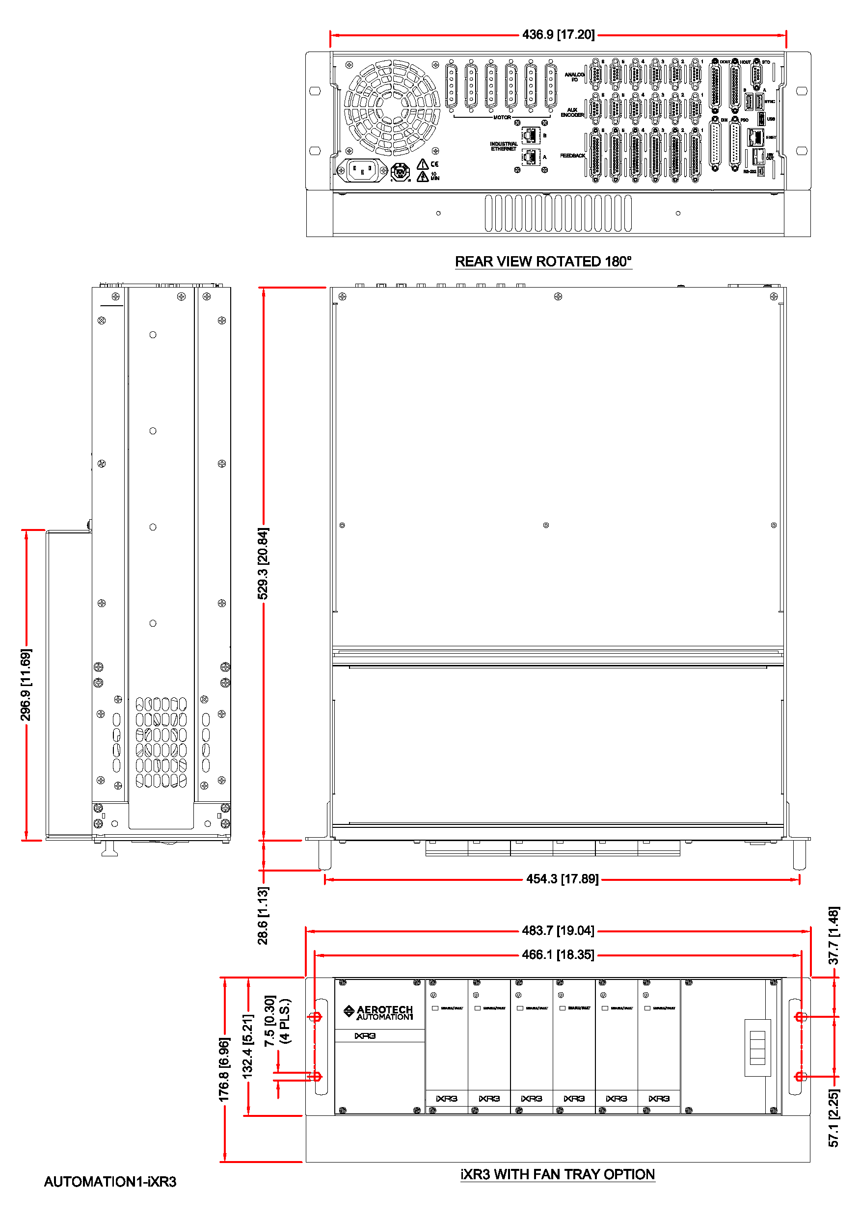
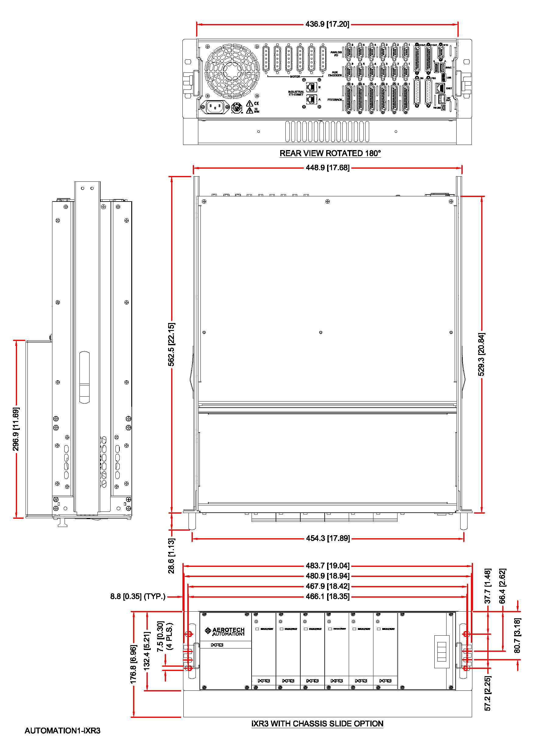
Dimensions
Automation1 iXR3, Rack-Mounted
Automation1 iXR3, Rack-Mounted with Drawer Slides
Ordering Information
Controller Configuration
| To configure and load the motion controller on the iXR3 drive, please configure and order an Automation1- iSMC intelligent controller with your iXR3 drive. The Automation1-iSMC configuration should include the iXR3 as the “hardware platform. |
Automation1 iXR3
| Option | Description |
| Automation1 iXR3 | Automation1-iXR3 - 3U, 19” Multi-Axis Servo Drive Rack with Motion Controller |
Line Voltage
| Option | Description |
| -VL1 | 120 VAC input |
| -VL2 | 240 VAC input |
| -VL3 | 100 VAC input |
| -VL4 | 200/208 VAC input |
- Line voltages VL2 and VL4 are not available with bus voltage selection VB7. Line voltages VL1 and VL3 are not available with bus voltage VB8.
Bus Voltage 1
| Option | Description |
| -VB1 | ±10 VDC (200 W power supply), bipolar |
| -VB2 | ±20 VDC (200 W power supply), bipolar |
| -VB3 | ±30 VDC (200 W power supply), bipolar |
| -VB4 | ±40 VDC (300 W power supply), bipolar |
| -VB5 | ±80 VDC (300 W power supply), bipolar |
| -VB7 | 160 VDC unipolar |
| -VB8 | 320 VDC unipolar |
- Bus voltages options are limited based upon other configuration selections.
Bus Voltage 2
| Option | Description |
| -VB0 | Not Wired |
| -VB1 | ±10 VDC (200 W power supply), bipolar |
| -VB2 | ±20 VDC (200 W power supply), bipolar |
| -VB3 | ±30 VDC (200 W power supply), bipolar |
| -VB4 | ±40 VDC (300 W power supply), bipolar |
| -VB5 | ±80 VDC (300 W power supply), bipolar |
| -VB6 (Future) | +150 VDC / -30 VDC Piezo |
| -VB7 | 160 VDC unipolar |
| -VB8 | 320 VDC unipolar |
- Bus voltages options are limited based upon other configuration selections.
Split Bus
| Option | Description |
| -SB0 | Axis 1-6 Bus Voltage 1 (/SPLIT BUS 1-6 |
| -SB1 | Axis 1 Bus Voltage 1, Axis 2-6 Bus Voltage 2 |
| -SB2 | Axis 1-2 Bus Voltage 1, Axis 3-6 Bus Voltage 2 |
| -SB3 | Axis 1-3 Bus Voltage 1, Axis 4-6 Bus Voltage 2 |
| -SB4 | Axis 1-4 Bus Voltage 1, Axis 5-6 Bus Voltage 2 |
| -SB5 | Axis 1-5 Bus Voltage 1, Axis 6 Bus Voltage 2 |
Controller Cards
| Option | Description |
| -CT0 | No controller card |
| -CTN | Controller Card without Multiplier |
| -CT1 | Controller Card with MX1 Multiplier |
| -CT2 | Controller Card with MX2 Multiplier |
| -CT4 | Controller Card with MX4 Multiplier |
Amplifier Cards
| Option | Description |
| -P0 | No Amplifier (P0) |
| -P1 | XSP3 Amplifier, 10 A Peak (P1) |
| -P2 | XSP3 Amplifier, 20 A Peak (P2) |
| -P3 | XSP3 Amplifier, 30 A Peak (P3) |
| -P4 | XSP3+, PWM+ Amplifier, 10 A Peak (-P4) |
| -P5 | XSP3+, PWM+ Amplifier, 20 A Peak (-P5) |
| -P6 | XSP3+, PWM+ Amplifier, 30 A Peak (-P6) |
| -L1 | XSL3 Amplifier, 10 A Peak (L1) |
- Linear amplifier option L1 requires bus voltage VB1, VB2 or VB4 and requires cooling option C1 or C2.
Cooling
| Option | Description |
| -C0 | Built-in fan pulls cooling air from left side |
| -C1 | Perforated covers above and below amp |
| -C2 | 1U-high fan tray for cooling |
- For C1 option, refer to the hardware manual for the external cooling requirements.
Line Cord
| Option | Description |
| -LC0 | No line cord |
| -LC1 | USA 120 VAC compatible line cord |
| -LC2 | USA 240 VAC compatible line cord |
| -LC3 | German compatible line cord |
| -LC4 | UK compatible line cord |
| -LC5 | Israel compatible line cord |
| -LC6 | India compatible line cord |
| -LC7 | Australia compatible line cord |
PSO
| Option | Description |
| -PSO1 | One-axis PSO firing (default) |
| -PSO2 | Two-axis PSO firing |
| -PSO3 | Three-axis PSO firing |
- Up to 3 independent PSO outputs can be programmed and used. Each independent PSO output requires an independent controller card.
Internal Shunt (Optional)
| Option | Description |
| -SI1 | Internal shunt, first bus |
| -SI2 | Internal shunt, second bus |
| -SI3 | Internal shunt, first and second bus |
- Internal shunts not available for all voltage bus options.
Integration (Required)
Aerotech offers both standard and custom integration services to help you get your system fully operational as quickly as possible. The following standard integration options are available for this system. Please consult Aerotech if you are unsure what level of integration is required, or if you desire custom integration support with your system.
| Option | Description |
| -TAS | Integration - Test as system Testing, integration, and documentation of a group of components as a complete system that will be used together (ex: drive, controller, and stage). This includes parameter file generation, system tuning, and documentation of the system configuration. |
| -TAC | Integration - Test as components Testing and integration of individual items as discrete components that ship together. This is typically used for spare parts, replacement parts, or items that will not be used together. These components may or may not be part of a larger system. |